ESP32 Socket Programming

 BSD socket API is A set of standard function calls to include internet communication capabilities in a product 


Other sockets API exists but the BSD socket is generally regarded as the standard. 


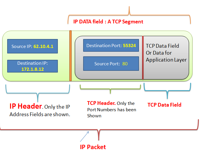
The sockets API makes use of 2 mechanisms to deliver data to the application level: ports & sockets. 


All TCP/IP stacks have 65,535 ports for both TCP & UDP 


A port is not a physical interface. Once an application has created a socket and bound it to a port, data destined for that port will be delivered to the application. 


A TCP/IP or UDP/IP packet is transmitted to a host, it eventually goes to the correct port then the socket conveys the packet’s data to the application 


Now Let’s go though some common socket calls 


socket()

Creates a socket & returns a reference number for that socket 

connect()

Creates a connection with another host 

send()

Send data over a connected socket 

recv() 

Receive data on the connected host 


Now we will go through this example https://github.com/espressif/esp-idf/tree/master/examples/protocols/sockets/tcp_client 


This example makes esp32 a tcp client. At the host computer,  a script will run as a TCP server. 


ESP32 has a lwIP stack, this stack has the socket API. 

The API can be found in this file 


esp-idf/components/lwip/lwip/src/include/lwip/sockets.h


To create a socket instance we have to use the following function of sockets.h 

static inline int socket(int domain,int type,int protocol)
{ return lwip_socket(domain,type,protocol); }


The type argument can be from the following values 

/* Socket protocol types (TCP/UDP/RAW) */
#define SOCK_STREAM     1
#define SOCK_DGRAM      2
#define SOCK_RAW        3


domain & protocol initialized as 

int addr_family;
int ip_protocol;
.......
.......
addr_family = AF_INET;
ip_protocol = IPPROTO_IP;


The socket() creates a socket and returns the socket number 

int sock =  socket(addr_family, SOCK_STREAM, ip_protocol);


Now we are going to understand another basic structure related to socket programming which is sockaddr_in 

/* members are in network byte order */
struct sockaddr_in {
  u8_t            sin_len;          //length of this structure
  sa_family_t     sin_family;       //AF_INET
  in_port_t       sin_port;         //transport layer port
  struct in_addr  sin_addr;         //the ip address
#define SIN_ZERO_LEN 8
  char            sin_zero[SIN_ZERO_LEN];
};


We have to create this structure type variable and use it to assign the server’s IP address to which we want to connect 


#define HOST_IP_ADDR CONFIG_EXAMPLE_IPV4_ADDR
#define PORT CONFIG_EXAMPLE_PORT


struct sockaddr_in dest_addr;
dest_addr.sin_addr.s_addr = inet_addr(HOST_IP_ADDR);
dest_addr.sin_family = AF_INET;
dest_addr.sin_port = htons(PORT);
inet_ntoa_r(dest_addr.sin_addr, addr_str, sizeof(addr_str) - 1);


Then this variable is used at the socket connection method 

int err = connect(sock, (struct sockaddr *)&dest_addr, sizeof(dest_addr));

This above function will connect to the server 

Similarly, other function such as send() and recv() of the API is used for communication 


The example code connects to wifi using example_connect() function, this is a blocking function and the block waits until a connection is established. the default event loop must be created before as wifi connection code is event based

tcpip_adapter_init();
ESP_ERROR_CHECK(esp_event_loop_create_default());
ESP_ERROR_CHECK(example_connect());


The code creates a freeRtos task that tries to connect to the server in an infinite loop and if connected then it communicates with the server in another infinite loop 


Running the Server Script

hassin@hassin-HP:~/esp/esp-idf/examples/protocols/sockets/scripts$ ifconfig


enx34298f9117bd: flags=4163<UP,BROADCAST,RUNNING,MULTICAST>  mtu 1500
        inet 192.168.11.96  netmask 255.255.255.0  broadcast 192.168.11.255


hassin@hassin-HP:~/esp/esp-idf/examples/protocols/sockets/scripts$ python3 tcpserver.py


Socket created
Socket binded
Socket listening


So the server is running on our host whose IP is 192.168.11.96 


Now we need to assign this IP address to CONFIG_EXAMPLE_IPV4_ADDR macro 


This can be done by idf.py menuconfig , in the same way, we assigned wifi SSID and Password values using the menuconfig  


After assigning the server’s IP address and Port , program esp32 . 

After getting connected to wifi , esp32 will connect to the server [host machine] and the server and client will communicate with each other 


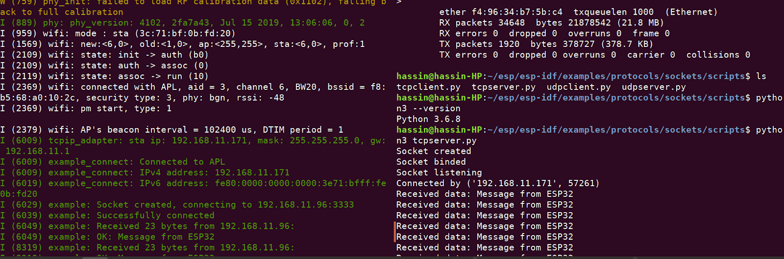
Here on the left side ESP32 log is printed and on the right side the python server’s log 

---------------------------------------------------------------------------------------------------------------------------------------------

Reference 

http://wiki.treck.com/Introduction_to_BSD_Sockets


Network Booting Ubuntu using iPXE and NFS


Network Booting

Using iPXE & NFS


Network Booting is a cool technique to boot the operating system in your machine from the network rather than the local hard drive. For example, in the above picture on the right is a desktop machine that does not have any hard drive, on the left we have a laptop. From the laptop, we will serve an OS over the network and the desktop machine will boot & run the OS completely over the network. The router will create the local network and act as a DHCP server. We will use iPXE & NFS mechanisms to do this. if you are interested to learn about the process in depth you can follow this link https://networkboot.org/fundamentals/ 


We will boot the Ubuntu 16.04.3 desktop version so firstly download the OS from http://releases.ubuntu.com/ and extract it. I am sharing my hands-on experience so my paths won't exactly match yours. My Host machine, which is the laptop in this case, is also running Ubuntu 16.04.3 desktop edition. 


First, install the dependencies 

~/diskless-node-pxe-setup$ sudo apt-get install liblzma-dev


Git clone the iPXE project’s source 

~/diskless-node-pxe-setup$ git clone git://git.ipxe.org/ipxe.git


~/diskless-node-pxe-setup$cd ipxe/src


Build the ROM for USB [for initial build test, later we will make the actual ROM] 

~/diskless-node-pxe-setup/ipxe/src$ make bin/ipxe.usb


We will use the NFS service to serve the OS so our host machine needs to have it 

Install NFS kernel Server 

~$sudo apt-get install rpcbind nfs-kernel-server


Open this file using gedit 

~$sudo gedit /etc/exports


Write the path of the extracted OS at the bottom of the file 

/home/hassin/Downloads/ubuntu-16.04.3-desktop-amd64     *(ro,async,no_wdelay,insecure_locks,no_root_squash,insecure,no_subtree_check)


Add NFS support to the PXE ROM 

~/diskless-node-pxe-setup/ipxe/src$ echo "#define DOWNLOAD_PROTO_NFS" >> config/local/general.h


Add script support to the ROM 

Open this file “ipxe/src/config/local/general.h

The IMAGE_SCRIPT macro should be defined [ not commented out] 


Take note of your host machine IP,

~$ ifconfig

for my machine, it was 192.168.0.100 


Create a script 

~/diskless-node-pxe-setup/ipxe-scripts$ cat > ubuntu16-live.ipxe


Open the script 

~/diskless-node-pxe-setup/ipxe-scripts$ gedit ubuntu16-live.ipxe


Add the following lines 

echo Hi, trying to boot ubuntu16-live
set server_ip 192.168.0.100
set nfs_path /home/ayx/Downloads/ubuntu-16.04.3-desktop-amd64
kernel nfs://${server_ip}${nfs_path}/casper/vmlinuz.efi || read void
initrd nfs://${server_ip}${nfs_path}/casper/initrd.lz || read void
imgargs vmlinuz.efi initrd=initrd.lz root=/dev/nfs boot=casper netboot=nfs nfsroot=${server_ip}:${nfs_path} ip=dhcp splash quiet -- || read void
boot || read void
echo Booting

Save it 


Now make the ROM by embedding the script 

~/diskless-node-pxe-setup/ipxe/src$ make bin/ipxe.usb EMBED=../../ipxe-scripts/ubuntu16-live.ipxe


Insert a pen drive, take note of its drive letter using the “Disks” utility app of ubuntu 

For my case, it was sdb 


~/diskless-node-pxe-setup/ipxe/src$ sudo dd if=bin/ipxe.usb of=/dev/sdb


Export the NFS shares of your host machine 

~$sudo exportfs -ra


Restart NFS-kernel-server 

~$sudo /etc/init.d/nfs-kernel-server restart


Remove the pen-drive , insert it into the desktop machine 

Make sure USB from the boot is enabled, 

Now everything okay then you will be able to use ubuntu over the network 


P10(1R) Dot Matrix Display Interfacing With Arduino

 The dot matrix display that I have is P10(1R), 

Don’t worry about the upper section being empty, I later did program it to show text 


Actual display Board 

Back Part [ PCB ] 


It is P10(1R)-DP4 536-V5 Type 


The closest datasheet that I got for this is http://www.hlec.com.cn/userfiles/files/20120928014657.pdf 


These Large Display Boards have multiple Units cascaded together. I call each unit a Panel 

So Multiple Panels being chained together make a large display board 


Here is how my board and it panels are chained to form the large display 


The Blue colored Double lines are the long jumper wires that chains each panel with another 


Now here is more info related to the Display 

  • Pixels per Panel is 32 (W)*16 (H) dots 

  • The board has 4 panels per chain 

  • The board has 2 chains 

  • So 8 panels in total 

  • So the total resolution is 320(w)x32(h) 


The pin interface is called HUB12, I have interfaced it with Arduino Uno 


Marking on the PCB 

HUB12 pinout at the datasheet 

Arduino Uno Pin Interface 


Here is where How you should connect Arduino Uno with the Display 


So you connect the Arduino Uno to the HUB12 interface to the panel located at [0,0] position 

Notice Panel 4 is chained to Panel 5 HUB12 interface by long jumper wire 


The Connection between HUB12 and Arduino Uno is 

Ref: http://cdn.shopify.com/s/files/1/0045/8932/files/DMDCON_DMDConnector.pdf?100730 


HUB12

Arduino

nOE

9

A

6

B

7

CLK

13

SCLK

8

R_DATA

11

GND

GND 


MOST Important: Use an External power Supply like this to power up the Display Board. Arduino is just for applying the logic. Don’t ever think it can power up the display board 😄


Now let’s prepare the Arduino Code 

At first, we have to install the libraries 


  1. Download this library https://github.com/freetronics/DMD 


Extract it and copy it to the Arduino libraries folder for example in my case   “/home/ayx/Arduino/libraries” 


     2. Open Arduino IDE and Install “TImerOne” Library using the “manage libraries” option 


Open Dmd_demo.ino sketch 

Change The code snippet like this 


//SPI.h must be included as DMD is written by SPI
#include <SPI.h>       
#include <DMD.h>       
#include <TimerOne.h>  
#include "SystemFont5x7.h"
#include "Arial_black_16.h"
#include "Droid_Sans_24.h"

//Fire up the DMD library as dmd
#define DISPLAYS_ACROSS 4
#define DISPLAYS_DOWN 2
DMD dmd(DISPLAYS_ACROSS, DISPLAYS_DOWN);

void ScanDMD()
{
  dmd.scanDisplayBySPI();
}
void setup(void)
{
  Timer1.initialize( 3000 );//period in microseconds to call ScanDMD.
  Timer1.attachInterrupt( ScanDMD );//attach the Timer1 interrupt to scan
  dmd.clearScreen( true );    //clearthe DMD pixels held in RAM
  dmd.selectFont(Droid_Sans_24);
}
void loop(void)
{
  dmd.clearScreen( true );
  delay(2000);
  dmd.drawMarquee("Scrolling Text",14,(32*DISPLAYS_ACROSS)-1,6);
}


Compile it and upload you, if everything is okay then you will see a large text scrolling 


Categories

Pages

Firmware Engineer

My photo
Works on Firmware, Embedded Linux, Smart Metering, RTOS, IoT backend

Contact Form

Name

Email *

Message *

Copyrighted by Hassin. Powered by Blogger.