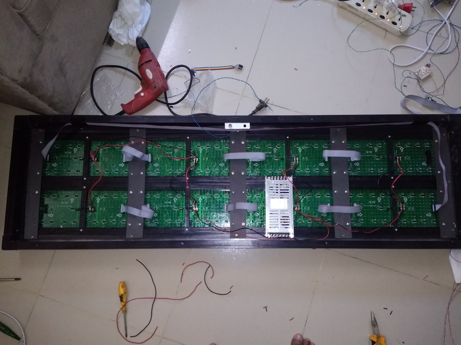
The dot matrix display that I have is P10(1R),
Don’t worry about the upper section being empty, I later did program it to show text


It is P10(1R)-DP4 536-V5 Type
The closest datasheet that I got for this is http://www.hlec.com.cn/userfiles/files/20120928014657.pdf
These Large Display Boards have multiple Units cascaded together. I call each unit a Panel
So Multiple Panels being chained together make a large display board
Here is how my board and it panels are chained to form the large display
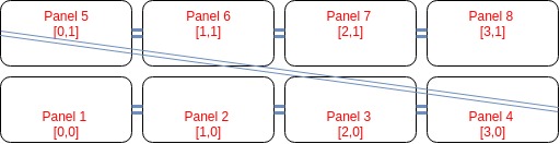
The Blue colored Double lines are the long jumper wires that chains each panel with another
Now here is more info related to the Display
Pixels per Panel is 32 (W)*16 (H) dots
The board has 4 panels per chain
The board has 2 chains
So 8 panels in total
So the total resolution is 320(w)x32(h)
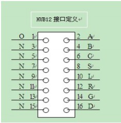
The pin interface is called HUB12, I have interfaced it with Arduino Uno
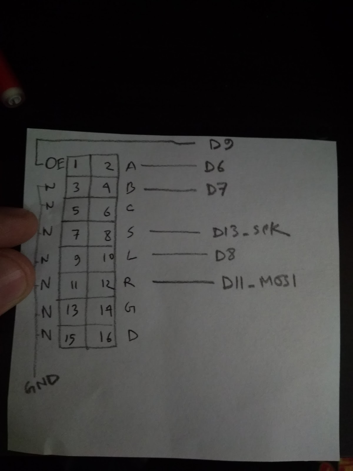
Here is where How you should connect Arduino Uno with the Display
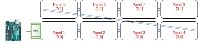
So you connect the Arduino Uno to the HUB12 interface to the panel located at [0,0] position
Notice Panel 4 is chained to Panel 5 HUB12 interface by long jumper wire
The Connection between HUB12 and Arduino Uno is
Ref: http://cdn.shopify.com/s/files/1/0045/8932/files/DMDCON_DMDConnector.pdf?100730
MOST Important: Use an External power Supply like this to power up the Display Board. Arduino is just for applying the logic. Don’t ever think it can power up the display board 😄

Now let’s prepare the Arduino Code
At first, we have to install the libraries
Download this library https://github.com/freetronics/DMD
Extract it and copy it to the Arduino libraries folder for example in my case “/home/ayx/Arduino/libraries”
2. Open Arduino IDE and Install “TImerOne” Library using the “manage libraries” option
Open Dmd_demo.ino sketch
Change The code snippet like this
Compile it and upload you, if everything is okay then you will see a large text scrolling


0 comments:
Post a Comment