A logic analyzer is a type of electronic test instrument that is used to capture and display signals in a digital circuit. It allows the user to see the timing and value of the signals on the circuit, which can help debug and troubleshoot the circuit. Logic analyzers are often used in conjunction with other test equipment, such as oscilloscopes and multimeters, to provide a complete picture of the behavior of a digital circuit
A logic analyzer typically connects to a PC through a USB or Ethernet interface, and the PC software reads the data from the logic analyzer by communicating with the analyzer over this interface. The software sends commands to the analyzer to configure it for the particular circuit being tested, and the analyzer sends the captured data back to the software for display and analysis. The specifics of how the software communicates with the logic analyzer will depend on the specific model of the analyzer and the software being used.
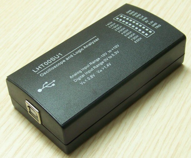
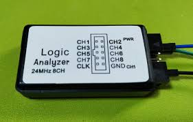
Here I will show how I have used a low cost LHT00SU1 logic Analyzer and setup it in Ubuntu
We will use PulseView as the graphical software
PulseView is a free, open-source software application for viewing and analyzing signals from electronic circuits. It is often used in conjunction with a logic analyzer, oscilloscope, or other types of test equipment to visualize and analyze the signals in a digital circuit. PulseView is developed by Sigrok, a free and open-source project for signal analysis, and is available for Windows, Linux, and MacOS. It provides a graphical user interface for viewing and analyzing signals, and supports a wide range of devices from various manufacturers.
Sigrok and PulseView are two separate but related software projects. Sigrok is a collection of software libraries and utilities for signal analysis, and provides the underlying infrastructure for connecting to and communicating with electronic test and measurement equipment. PulseView is a graphical user interface built on top of the Sigrok libraries, and provides a convenient way for users to visualize and analyze signals from their circuits.
In order to use PulseView, you will need to have the Sigrok libraries installed, because PulseView relies on the Sigrok libraries to communicate with the test equipment and acquire the signals. Installing both PulseView and Sigrok will ensure that you have all the necessary components to use PulseView to view and analyze signals from your circuits.
To install PulseView and Sigrok in Ubuntu, you can follow these steps:
Open a terminal window on your Ubuntu system.
Install the Sigrok package by running the following command:
Install the PulseView package by running the following command:
Once the installation is complete, you can launch PulseView by running the following command:
PulseView should open and you can start using it to view and analyze signals from your electronic circuits
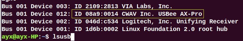
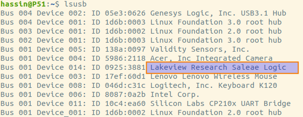
You can check the connection of the Device using the following command
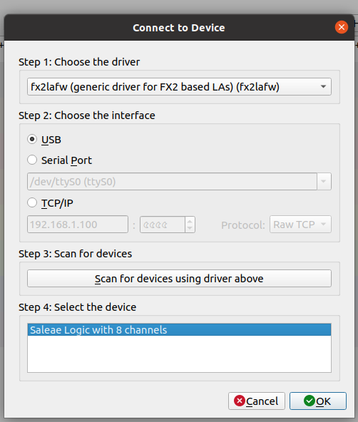
To use PulseView, you will need to connect your logic analyzer or other test equipment to your computer and install the necessary drivers. Once the hardware is set up and the software is installed, you can launch PulseView and follow these steps:
In PulseView, select the type of device you are using from the list of supported devices.
Configure the device settings, such as the sample rate and the channels you want to capture, using the options in the Device Settings panel.
Click the Start button to begin capturing signals from the circuit.
Use the controls in the Signal View panel to view and analyze the captured signals. You can zoom in and out, scroll through the captured data, and apply filters and measurements to the signals.
Use the controls in the Device Control panel to control the operation of the device, such as triggering the capture of a signal or setting the voltage levels on the device's outputs.
Use the File menu to save the captured data or export it to another format for further analysis or sharing.
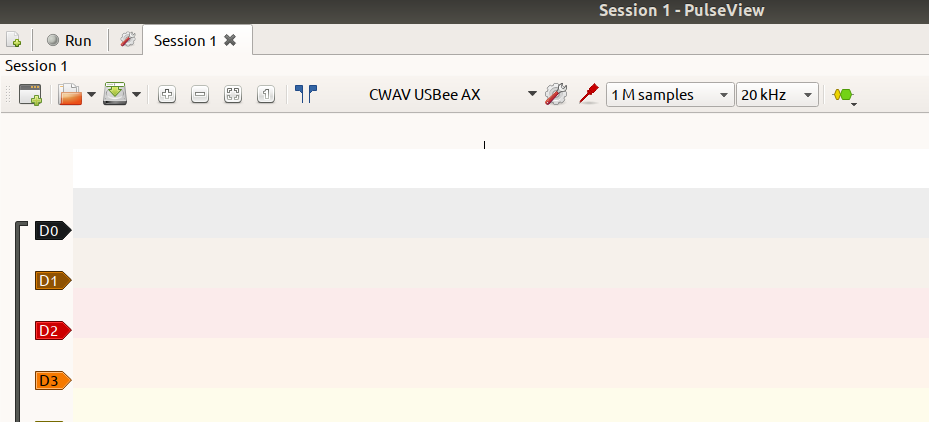
PulseView provides a number of other features and options, and you can explore the application and experiment with its capabilities to learn more about how to use it effectively. An Example Screenshot is given below
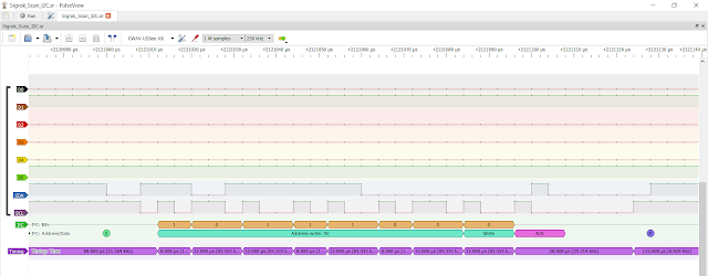 |
| Sigrok software Example Snippet |


