Introduction
This Post proposes a specification of smart water meters, bridges, gateways & a centralized IoT platform for smart water Meter AMI. The IoT platform performs the SCADA role supporting both Postpaid & prepaid meters. The proposal makes an effort to demonstrate how the combination of LPWAN technology like Lorawan with industry-proven wmBus Protocol can solve current water meter reading problems. The solution is both efficient and cost-effective.
As part of AMI (Automated Metering Infrastructure) both Head End System (HES) and MDMS (Meter Data management System) reside at Cloud / Server Machines. According to LoraWAN architecture Here HES is equivalent to LoraWAN network Server and MDMS to the Application Server
The rest of the IoT components and their role are described below
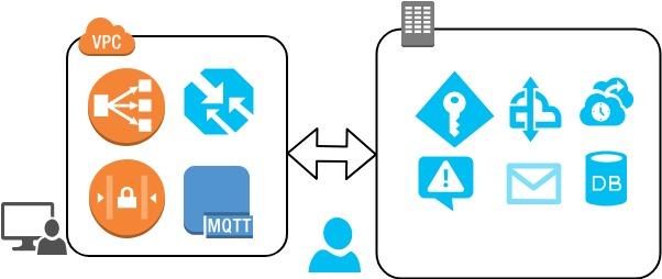
Overall Functional Block Diagram:

Basic Communication Flow:
Water Meters are mostly placed underground. We assume that The meters are wMBUS type. A standard water meter can also have a wmBUS communication module on top. The bridge devices located at building premises communicate with them as per wMBUS protocol at its downlink. Then at uplink the bridge acts as a Lora node & communicates with the LoraWan gateways located at Towers. The loraWan Gateways in turn communicate to the HES by LoraWAN protocol. The HES supports Lorawan protocol and along with the MDMS it creates an IoT SCADA platform for the water Meters
wMBUS protocol
wMBUS or Wireless M-Bus is a European standard EN 13757-4. wMBUS uses the classical energy-saving FSK radio modulation. There are 3 frequencies used in the Wireless M-BUS: 868MHz, 433MHz & 169MHz. It is a basic star-type network. The modes in wMBUS are:
At Mode N at 169 MHz the best range is achieved. The line of Sight communication range can be more than 5 km. In urban areas, it can be between 1-2 Km. But for our use case of water metering, we will use modes S, T or C. More particularly we will use Mode S2, T2 & C2 as they offer bidirectional communication. In mode S, T & C at 868 MHz the range will be a few hundred meters at LOS, and typically 50-100 meters among buildings. At 433MHz the range will be somewhat longer.
LoraWAN protocol
Lora is the Physical Layer for Long range communication defined by Semtech. LoraWan is the MAC protocol on top of Lora Defined by the Lora Alliance for LPWAN networks. Contrary to wMBUS the Lora modulation is a chirp spectrum type that maintains the same Low power characteristics as FSK modulation but significantly increases the communication range. The protocol and network architecture by LoraWan determines the battery life, network capacity, quality of service, and security.
Spreading factors ranges from SF7 to SF12
The device Classes of LoraWan are
Our Bridge module will be class A type as this class provides the lowest power consumption
The range between gateways and bridges is 3-5Km in urban areas on average, depending on gateway positions. Typically > 10km in rural areas.
Installation Guideline
The necessity of the bridge modules:
Considering the Meters being underground the wMBUS wireless range can be often limited to 50m so an additional longer range RF technology is needed to forward the radio packet to the HES. So we have chosen Lora for the longer range Rf technology Our wMBUS-Lorawan Bridge device solves this problem, it communicates with wMBUS-enabled meters and relays the packets to the LoraWAN network. The Gateways get data from these bridges as per LoraWan protocol and transfer them to HES.
wMBUS protocol is a proven technology in the metering standard and LoraWan is the leading open source LPWAN technology. Our solution has merged both the solutions in a secured and scalable manner for future interoperability.
The Bridge Module plays a significant role in solving long-distance bi-directional communication. It is battery-operated and can be installed with minimum hassle. It is of low cost and can connect up to hundreds of meters forming a NAN network of its own. Later it joins the WAN network consisting of the Gateways
One Might ask why not use Lora Protocol directly at Water Meter level and remove the necessity of using wmBUS as the communication origin. Actually various Water Meter Installation companies have found that Lora signals do not penetrate well when Devices are underground. As water meters are mostly underground thus The mix of wmBUS and LoraWAN is being proposed
Installation Position of the Bridge modules:
Our bridge module is battery-operated and very easy to install anywhere. We advise it to place it at nearby electricity poles / inside buildings. The Bridge module is far less costly than the Gateway device and it can run for 10 years on 2 batteries which are replaceable.
The Bridge module can be inserted onto a DIN rail using a mounting clip. The Din rail can be easily screwed onto the concrete wall
Bridge Module Antenna: For optimal RF performance it should not be placed near any metal obstacles. To extend the range the bridge module can be equipped with an external antenna as it has the SMA connector
Bridge Module Power Supply: the bridge module has to be battery-powered. It can consist of 2 1.5V AA size batteries connected in series. These are replaceable too. The battery lifetime could be up to 8-10 years.
Installation Position of the Gateway:
Our gateway devices are costlier than the bridge module and we advise it to install at BTS stations so that they can get the maximum LOS (Line of Sight) targeting the bridge modules. Another suitable location is the poles of Electricity distribution utilities.
Communication Patterns
Communication Mechanisms can be subdivided into the following parts.
Water Meter To Bridge Communication
Bridge module To Gateway Communication
Gateway to HES communication
HES to MDMS communication
Water Meter to Bridge Module Communication

In this communication part, the a wMBUS LoraWan Bridge module acts as the wMBUS master and the slaves are the wMBUS supported meters. If the water Meter does not have wMBUS communication as built-in then a wMBUS communication module should be inserted on top of it.
The MBUS telegram formats are
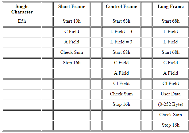
Typical Water Meter related DIF (Data information Field)
The Bridge module embeds the wMBUS packet into the Lorawan packet and the bridge transfers the packet to its uplink i.e to the LoraWAN gateway. If a data packet is more than the maximum payload size of the lorawan protocol [Depends on SF] then the packet will be transferred in multiple lorawan packets. The reconstruction of the packet is done in the HES
Bridge Module to Gateway Communication

Support of Lora-based Meters
The bridge module's uplink supports the Lora PHY layer. If a Meter is near Gateway or which is not underground and can be directly communicated to the Gateway then it can have the Lora Node module and communicate directly to the gateway bypassing the bridge module. In that case, the Lora payload format must be according to the wMBUS protocol. In this Type, the Water Meter’s communication Medium will be based on lora-PHY-supported RF chips.
The Gateways will also have Lora-PHY supported RF chips having multiple channels to receive the Lora signals. The Communication Protocol Between the meters and the gateway will be based on the LORAWAN protocol.
RF-Chip Selection:
It is suggested to use sx1301 as the Rf-chip for the Gateway
It is suggested to use sx1276/77/78 as the Rf-chip for the Water Meter Nodes
The Lora TM packet structure

Here The Payload will hold Water Meter Data.
Regional Parameters for Bangladesh
According to LORAWAN regional parameter v1.1 the channel Plan can be EU433 or EU863-870

The Lorawan packet Format

The Above picture shows the breakdown of the Protocol Format
Types of Messages & Commands
Uplink/downlink messages
Uplink messages are sent by end devices to the network server
Downlink messages are sent by the network server to the end devices.
Message types: Confirmed / unconfirmed / proprietary
Data messages (both downlink & uplink) can be confirmed or unconfirmed.
A confirmed message has to be acknowledged by the receiver.
MAC commands
Network commands are added to a message or sent in a separate frame, based on request/answer between the end-device and network server. This is managed by the HES aka Network server.
STS and Token System
In Prepaid Metering STS(standard Transfer System) is widely followed and Utility has to send tokens to Meters via the LoraWAN protocol
Confirmed & Unconfirmed Data relation To STS token
End nodes will send data periodically as send unconfirmed() . STS token result will be sent to the server by Node as send confirmed(). HES should return ACK. if ACK is not received, the node will re-transmit the result message a maximum of times.
Device activation on the network
Here we can choose between the following 2 methods.
Over The Air Activation (OTAA)
End-device follows a join procedure prior to exchanging data with the network server.
Devices can attach to any LoRa network,
Security keys can be updated from time to time (session based).
Device reboots are easily detected.
The application server has to answer to join requests each time a device (re)starts, it will generate more downlink traffic.
Activation by Personalization (ABP)
The end device is already pre-registered on the network.
DevAddr, NwkSKey & AppSKey are stored in the end-device and Network Server.
Simpler from the application server point of view node tied to a particular network or must be registered with exactly the same keys
OTAA is more secure and scalable, It is advised to follow OTAA
Device Identification & Authentication related parameters
Adaptive data Rate
The End node which is the bridge module has ADR enabled. To maximize both the battery life of the end-devices and overall network capacity, the HES itself will manage the data rate and RF output for each end-device individually by means of an adaptive data rate (ADR) scheme. If The Water Meter itself has the Lora communication Module then it should have ADR support.
LoraWAN uses ISM frequency Bands, thus the vendor must ensure that the communication is not exceeding the permitted time using the chosen frequency channel [for example 1% of time]. The HES will Cutoff service to those nodes which exceed the maximum number of sending frames in a period of time
Bridge Module Class Type
The Lorawan Supported Bridge Modules should be of Class A type [Bi directional End devices] . In this type uplink transmission is followed by 2 downlink receive windows.
Communication Patterns (continued)
Gateway to HES Communication

The Lorawan Gateway communicates to the HES by GPRS/ Ethernet / Wifi.
If a Lora packet received by the gateway is successfully decrypted then the payload will be forwarded towards the HES.
The Gateway has the provision to change its Target HES IP and PORT via desktop software/web browser. The provisions are available via GPRS, Ethernet, USB, RS485 or RS232. Currently the Gateway also has an embedded web server over LAN. Utility’s MDMS will access it by web browser under the same local network or they can access it over the WAN.
Configuration Parameters of the Gateway
The Admin can Input the following parameters to the gateway
Target HES IP & Port
Channel Plan
Gateway ID
Network Session Key [Area Wise]
The Gateway can have a GPS also. This provides the benefits of localizing the gateway within an area.
As per the nature of the modulation used in Lora which is a chirp. The gateway is able to collect reflected RF-signals too. Installation positions should be chosen For the Wide area coverage and Best Line of Sight operation.
Communication Standard between Lora Gateway and HES
The communication between Lora Gateway & HES is based on MQTT technology. The gateways have “packet forwarder UDP protocol” implemented. On top of it the Gateway Lora Gateway Bridge service is also implemented. The HES must support both LoraWan 1.0 & LoraWan 1.1 specifications. The HES by default provides application data over MQTT protocol. It also provides REST APIs to enable integration with external services. The LoRaWAN network architecture is a star-of-stars topology in which gateways are a transparent bridge relaying messages between the water meters via the bridge modules and a HES in the back-end. Gateways are connected to the network server via standard IP connections Over GSM-GPRS while end-devices use single-hop wireless communication to one or many gateways.
Network Server (HES) to Application Server ( MDMS ) Communication:
The responsibility of the HES is the de-duplication and handling of received uplink frames received by the gateway(s), handling of the LoRaWAN mac-layer, and scheduling of downlink data transmissions.
The MDMS is responsible for the device “inventory” part of a LoRaWAN infrastructure, handling of join-request and the handling and encryption of application payloads. It offers a web UI where users, organizations, applications and devices can be managed. For integration with external services, it offers a restful API. Devices are sent or received over MQTT, HTTP/HTTPS
End-to-End Security

wMBUS Authentication:
The bridge module authenticates each device according to the wmBUS protocol. The allowable slave device IDs are assigned to the bridge modules by The Application server [MDMS] via the HES and GW. After the authentication phase bridge module starts joining the meters to the Network server [HES]. This is done following OTAA mechanism
Network Session:
The Bridge Modules can send data to multiple gateways. The Bridge module is first assigned a Network Key by the HES. The bridge module then assigns this network key prior to sending the data of the meters which are under its wmBUS network thus a network session is created. This Network session is encrypted by the NwkSKey. Gateway upon receiving a lorawan packet tries to decrypt it by the NwsKey and if it is not passed then the packet is dropped. This prevents man in the middle attack
Application Session:
Each Manufacturer can encrypt its meter data with its own encryption key. These keys are stored in the MDMS. The manufacturer can encrypt its meter data in the wmBUS packet by its AppSkey. These packets are conveyed by the bridge module and the HES and lastly decrypted in the MDMS.
Uniform Operation
The Gateway will be as per LoraWAN protocol. Under this Protocol, the Gateway will receive any Lora-PHY signals as captured and it will then decrypt the payload by the network key which is assigned to it. If the payload falls under the network then the packet will be forwarded to the HES, if not then the packet will be dropped. In this way, the Gateway will be able to receive multiple vendor’s water meter data. This way of operation establishes a scalable & uniform communication between multi-vendor’s water meter & multi-vendor gateway. The Gateway does not need to know the manufacturer information as it only decrypts the packet by the network assigned to it. All the Gateways will be assigned the same network key and the same HES target IP & port will be set to them. In this way, The utility can also rely upon other vendor Gateways too achieve a future-proof scalable AMI.
Prepaid Meter Solution
Prepaid type Water Meters have a valve inside. The Water Meter is as by STS standard. It provides a complete solution for utilities, and property owners to better manage revenues from water services.
Key Features Of a Prepaid Meter
STS compliant
Adjustable low credit alarm level
Adjustable maximum water limit
Periodic Valve Protection
Low Battery Warning
Protection against magnetic interference
Complete seal of the enclosure
Token Types
Data parameters related to STS
Unified Payment Operation
Each Manufacturer embeds its own VDDK inside the meter and deploys them in the field. Aligning with STS org VDDK are stored in a TPM-enabled Secured module. Interfacing with a secured module and generating a token from it is implemented in the Application Server ( MDMS ). MDMS generates VUDK from the Secured Module and transfers it to the meters by key change token mechanism, afterwards STS token generation is performed according to Consumer vending. Tokens are sent to the meters over the loraWan network.

The MDMS can integrate any vendor STS meters according to the STS process. The Security is maintained by the STS organization by managing the Secured Module. End Consumers can pay in advance via different payment options such as credit card / mobile banking.
Conclusion
The discussion above is an Ideal guideline for Designing a Full stack Smart Water Meter AMI from scratch. If you need more guidelines or want to utilize similar communication methods implemented for other complex use cases then Please feel free to reach out to me Hassin Ayaz


0 comments:
Post a Comment