ESP32-UART-programming

In this post, we will see how the ESP32 UART peripheral can be programmed

UART stands for Universal Asynchronous Receiver Transmitter

  • ESP32 has 3 UART controllers
  • These controllers are connected to the GPIO matrix allowing you to assign the UART peripherals to any of the GPIO
  • Communication speed is up to 5 Mbps
  • All the 3 UART interfaces can be accessed by the DMA controller or directly by the CPU

If you look closely you can see other than the usual TX RX lines there are RTS and CTS lines.

  • what are RTS / CTS lines?

RTS / CTS flow control mechanism is part of the RS232 Standard. These 2 Lines help Transmitter and receiver to alert each other before transmission takes place.

  • RTS means Request to Send
  • CTS means Clear to Send

You can read more on this here flow-control.


ESP32 UART provides hardware management of the CTS and RTS signal lines & the corresponding software flow control.

Now Let's get into programming the UART peripheral

Set ESP32 Default Console Output

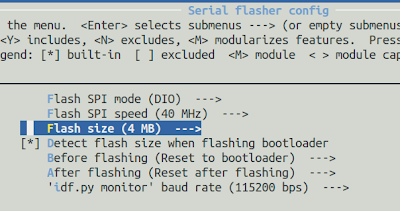
Esp-SDK uses menuconfig to set different configurations for the chip

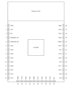
  • By default, UART0 is selected as the controller for the console output
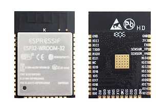
  • The UART0 is mapped to GPIO01(TXD0) & GPIO3(RXD0) pins

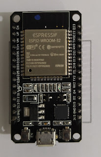
In the ESP32-devkit board, these GPIO lines are connected to the CP2101 USB-UART module. So whenever we use printf() in the code to print something the printf function is internally using UART0 peripheral. Additionally, this UART0 is also used by the bootloader to print its debug log and take the binary image from the host machine during the flash process

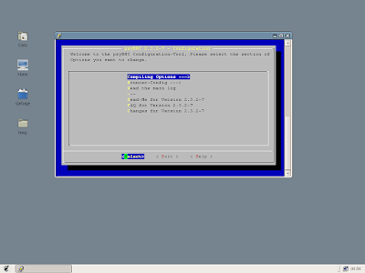
If you open menuconfig in any of the example projects you can see the default settings as

hassin@hassin-HP:~/esp/hello_world$ idf.py menuconfig

Code Analysis 

We will go through the esp-idf/examples/peripherals/uart/uart_echo code-link example to understand how we should use the UART of ESP32. this is a very basic project and does not use RTS CTS software flow control.

In this project, the code sets 2 GPIOs to work with the UART1 controller. Any data received at the UART1 controller is echoed back to the same UART controller i.e UART1

So you need to connect a USB-UART module to the UART1 based GPIO pins and open a terminal app in your host machine

First, we have to create & set a uart_config_t structure type that varies according to our need

    /* Configure parameters of an UART driver,
     * communication pins and install the driver */
    uart_config_t uart_config = {
        .baud_rate = 115200,
        .data_bits = UART_DATA_8_BITS,
        .parity    = UART_PARITY_DISABLE,
        .stop_bits = UART_STOP_BITS_1,
        .flow_ctrl = UART_HW_FLOWCTRL_DISABLE
    };

Then we have to set the structure to one of the 3 UART controllers

uart_param_config(UART_NUM_1, &uart_config);

The following function sets the internal UART Signals to GPIO pins

uart_set_pin(UART_NUM_1, ECHO_TEST_TXD, ECHO_TEST_RXD, ECHO_TEST_RTS, ECHO_TEST_CTS);

Afterward, we install the UART driver using the following SDK API

esp_err_t uart_driver_install(
  uart_port_t uart_num, 
  int rx_buffer_size, 
  int tx_buffer_size, 
  int queue_size, 
  QueueHandle_t* uart_queue, 
  int intr_alloc_flags);

understanding the API parameters is important. The following table describes it

Parameter type
Argument
                   Meaning

uart_port_t uart_num UART_NUM_1                        Set your UART controller
int rx_buffer_size BUF_SIZE*2                        The RX buffer size
int tx_buffer_size 0                        If 0 then TX function will block task until all data is sent
int queue_size 0
QueueHandle_t* uart_queue NULL                         If used then a new queue handle is created to provide access to UART events
int intr_alloc_flags 0                         Related to interrupt

We call the function with proper values

uart_driver_install(UART_NUM_1, BUF_SIZE * 2, 0, 0, NULL, 0);

The following function is used to read bytes from the UART buffer.

int uart_read_bytes(
  uart_port_t uart_num, 
  uint8_t* buf, 
  uint32_t length, 
  TickType_t ticks_to_wait);
int len = uart_read_bytes(UART_NUM_1, data, BUF_SIZE, 20 / portTICK_RATE_MS);

Then to Send data to the UART port from a given buffer and length the code use this function

int uart_write_bytes(
  uart_port_t uart_num, 
  const char* src, 
  size_t size);
uart_write_bytes(UART_NUM_1, (const char *) data, len);

As the UART driver's parameter tx_buffer_size is set to zero. This function will not return until all the data have been sent out. Otherwise, if the tx_buffer_size > 0, this function will return after copying all the data to the tx ring buffer & later UART ISR will move data from the ring buffer to TX FIFO gradually.


Build & Flash
hassin@hassin-HP:~/esp/esp-idf/examples/peripherals/uart/uart_echo$ idf.py -p /dev/ttyUSB0 flash monitor
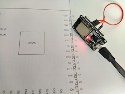
Connection Connect the USB-UART module to the ESP32 board

Then open a Serial terminal app to send data to the UART1 controller, I have used Arduino IDE Serial terminal

Now whatever you send will get echoed back to your serial terminal App

ESP-32 Boot-up Sequence

When We start to learn a microcontroller or SoC, we want to write a lot of code quickly and make use of all the available features/peripherals. But I think acquiring proper knowledge of the boot sequence of an MCU is also very important.

I have seen embedded products getting stuck/hung in boot mode. Most of the time the reasons are developers not spending enough time on reading the datasheet & missing out on important hardware notes or fuse bit settings. Knowing the exact booting information will also help the programmer to plan or debug better. In this blog post, I would like to explain how ESP32 gets boot-ed. I hope the read will be an enjoyable one! :)

ESP32 Internal

Here in the picture below you can see the internals of an ESP32 module . if you decap the metal plate of the module you will see inside It has mainly 2 silicon chips one is the esp32 mcu and other one is a SPI based flash chip.

Now let's look into the following block diagram for better understanding what is inside.

Here you can see that the ESP32 module has one mcu and one flash chip, both being connected via SPI. The esp32 microcontroller itself has a small ROM . The First Stage bootloader resides in the ROM . It is pre-programmed by Espressif (the silicon vendor).

The important addresses are

Type Address Offset
Application 0x10000
Partition Table 0x8000
2nd stage Bootloader 0x1000

The microcontroller has 2 CPU , these are

  • PRO CPU
  • APP CPU

Partition Table & FLash

Now let's understand the partition table . Just like we divide our laptop's hard disks into different partitions for example Drive [ C: D: E:]. One can divide the SPI flash of the ESP32 module into multiple partitions. different partitions can hold different types of data (e.g. calibration data, filesystems, parameters storage, OTA backup etc).

Unlike other mcu manufacturers espressif gives us a lot of flexibility in flash space orientation provided the Flash is external to the mcu itself . Very clever and modular design! Obviously this type of SoC design has some drawbacks but we can talk about that later . Now back to partitioning . In order to implement the dividends A partition table needs to be flashed at memory address 0x8000. This table tells what kind of data gets into which partition. This can be configured using the menuconfig

Reset Sources

Before explaining the boot sequence we should know which are the reset sources of our mcu ESP32 microcontroller has the following reset sources

  • Wake up from deep sleep
  • Power on reset (POR)
  • Watchdog (WDT)
  • Software (SWT)

Flashing hardware tool Connection

The RTS & DTR lines of USB-UART chip CP2102 is connected to GPIO0 & EN pin of the mcu as shown in the above picture & below table

ESP32 Pin Serial Pin(CP2102)
EN RTS
IO0 (GPIO0) DTR

Flashing command

When we build our project using idf.py of the esp-sdk, the built tool builds the bootloader binary file along with the application binary, for example during the build of the gpio example 2 bin files get generated named bootloader.bin & gpio.bin.

esptool.py -p /dev/ttyUSB0 -b 460800 --after hard_reset write_flash --flash_mode dio --flash_freq 40m --flash_size 4MB 0x8000 partition_table/partition-table.bin 0x1000 bootloader/bootloader.bin 0x10000 gpio.bin

Boot Sequence

Following the reset of any kinds listed above, ESP32 will go through the following bootup sequence.

  1. MCU resets

  2. PRO-CPU runs & does all the initialization while APP-CPU is held in reset

  3. CPU jumps to Reset vector

  4. Reset vector is located at address 0x40000400 in the ROM

  5. Startup code(1st stage bootloader) is called from reset vector

  6. 1st stage bootloader checks Reset reason

  7. 1st stage bootloader checks if UART or SDIO (sd-card) download mode is requested or not , if so it waits for the incoming binary code to be downloaded (This event happens during flashing process)

  8. Assuming flashing command is being executed and GPIO0 is held LOW on reset by the flashing hardware (CP2102) then The ESP32 will enter into the bootloader mode.

  9. If the 1st stage bootloader finds that UART download should be performed then it does so and puts the received bootloader.bin at offset 0x1000 in flash. ( This bootloader is called the 2nd stage bootloader). then it writes the application binary at the pre-set offset Address (0x10000)

  10. So once 1st stage bootloader finishes writing the binary data given by esptool.py, it jumps to 2nd stage bootloader.

  11. Getting jumped from 1st stage bootloader, The 2nd stage bootloader takes in control and starts running, at start it prints some informations via UART0 , reads partition table from offset 0x8000 & prints the partition table

  12. after 2nd stage bootloader gets done printing some useful information, PRO-CPU prints some other info and transfers the control over to the the APP-CPU

  13. APP-CPU starts executing the Application binary machine instructions & Starts the FreeRtos Scheduler thus our application begins running

  14. During operation / normal runtime If any of the reset sources triggers then all the sequence happens again.

  15. If The First stage bootloader does not get any data over UART within a fixed time then timeout occurs and it jumps to the 2nd stage bootloader and all the subsequent steps occur as explained above.

I (74) boot: Chip Revision: 1
I (74) boot_comm: chip revision: 1, min. bootloader chip revision: 0
I (40) boot: ESP-IDF v4.1-dev-474-g2e6398aff 2nd stage bootloader
I (41) boot: compile time 18:30:23
I (41) boot: Enabling RNG early entropy source...
I (47) boot: SPI Speed      : 40MHz
I (51) boot: SPI Mode       : DIO
I (55) boot: SPI Flash Size : 4MB
I (59) boot: Partition Table:
I (62) boot: ## Label            Usage          Type ST Offset   Length
I (70) boot:  0 nvs              WiFi data        01 02 00009000 00006000
I (77) boot:  1 phy_init         RF data          01 01 0000f000 00001000
I (85) boot:  2 factory          factory app      00 00 00010000 00100000
I (92) boot: End of partition table
I (96) boot_comm: chip revision: 1, min. application chip revision: 0
I (191) boot: Loaded app from partition at offset 0x10000
I (191) boot: Disabling RNG early entropy source...
I (192) cpu_start: Pro cpu up.
I (196) cpu_start: Application information:
I (201) cpu_start: Project name:     gpio
I (205) cpu_start: App version:      v4.1-dev-474-g2e6398aff
I (212) cpu_start: Compile time:     Oct 28 2019 16:42:49
I (218) cpu_start: ELF file SHA256:  722f4baa50cdbbc9...
I (224) cpu_start: ESP-IDF:          v4.1-dev-474-g2e6398aff
I (230) cpu_start: Starting app cpu, entry point is 0x40080fec
0x40080fec: call_start_cpu1 at /home/hassin/esp/esp-idf/components/esp32/cpu_start.c:276

I (0) cpu_start: App cpu up.
I (240) heap_init: Initializing. RAM available for dynamic allocation:
I (298) cpu_start: Starting scheduler on PRO CPU.
I (0) cpu_start: Starting scheduler on APP CPU.

By embedding the 1st stage bootloader in the esp32 mcu, espressif has made programming of the module very easy. In addition, as the UART interface is chosen for the transfer, the whole process becomes much easier, not requiring complex tools like JTAG / ISP programmers. Still one can use the JTAG interface for programming / debugging but I will cover that in a later post.

References:

ESP32-GPIO-programming

In this blog post, we will learn about esp32 GPIO programming we will use the following example as a reference

https://github.com/espressif/esp-idf/tree/master/examples/peripherals/gpio

GPIO basic Info

ESP32 has 34 GPIO pin. Configuration Options are

  • internal pull-up
  • internal pull-down
  • high impedance

The input can be set to edge trigger/level trigger to generate CPU interrupts

Now we will go through the example program provided by esp-idf to understand how we should configure & use GPIO of the ESP32 microcontroller

Our Goal

  • Configure 2 GPIO pins as output
  • Configure 2 GPIO pins as input
  • Enable the interrupts of the input pins.
  • Toggle the output pins in an infinite while loop 
  • create interrupt events for the input pins
  • The code should handle the events and print them via the debug interface

We will need to manually connect the input and output pin pairs using jumper wires.

Pinout

The pinout of the esp32 module is

The Pins used in this project are

Pin Table

Pin Mode
GPIO18                                   output
GPIO19                                   output
GPIO4                                   Input pulled up, interrupt from rising and falling edge
GPIO5                                   Input pulled up, interrupt from the rising edge


The above picture shows how I shorted the pin pairs

Note

In AVR programming we normally see that GPIO pins are grouped, for example, PORTA, PORTB, etc. but in ESP32 all the pins are in One Group and as the pin numbers are more than 32 so we have to use 64-bit masking to select the pins

#define GPIO_OUTPUT_IO_0    18
#define GPIO_OUTPUT_IO_1    19
#define GPIO_OUTPUT_PIN_SEL  ((1ULL<<GPIO_OUTPUT_IO_0) | (1ULL<<GPIO_OUTPUT_IO_1))

Here in the example code, you can see that the 64bit value is used for bit masking (ULL = Unsigned Long Long = 64bit )

Another reference is the gpio_config_t structure type in gpio.h file provided by the esp-idf SDK, here uint64_t size is used for bit masking

/**
 * @brief Configuration parameters of GPIO pad for gpio_config function
 */
typedef struct {
    uint64_t pin_bit_mask;          /*!< GPIO pin: set with bit mask, each bit maps to a GPIO */
    gpio_mode_t mode;               /*!< GPIO mode: set input/output mode                     */
    gpio_pullup_t pull_up_en;       /*!< GPIO pull-up                                         */
    gpio_pulldown_t pull_down_en;   /*!< GPIO pull-down                                       */
    gpio_int_type_t intr_type;      /*!< GPIO interrupt type                                  */
} gpio_config_t;

In the main() function first, the output pins are configured using the io_conf variable of type gpio_config_t.

Throughout your esp32 programming journey, you will have to use these kinds of structures provided by the esp-idf framework.

So you can see that using the structure above you can set multiple pins according to your needs. Only the Bit masking should be right

Next, the code has to set both GPIO4 & GPIO5 as Input pins with rising edge detection enabled, using the same structure.

But then as GPIO4 needs to be both rising & falling detection enabled so the pin’s interrupt mode is changed using the following function

//change gpio interrupt type for one pin   
gpio_set_intr_type(GPIO_INPUT_IO_0, GPIO_INTR_ANYEDGE);

Now let’s look at the following diagram where the overall working mechanism of the code is depicted

Analysis

Here you can see that an infinite loop in the main is toggling GPIO18 & GPIO19. As GPIO18 & GPIO19 are shortened to GPIO4 & GPIO5 so the toggling in turn creates interrupt events which are captured by the gpio_isr_handler() function.

The handler fills the gpio_evt_queue. In the Code, there is a freertos task named gpio_task_example() which is blocked waiting on the gpio_evt_queue, So whenever an item is available in the queue the task starts running. The item passed to the task is actually the pin number from where the interrupt is generated. the task prints the Pin number and its current state via the debug port

Code snippet for creating FreeRtos Queue

static xQueueHandle gpio_evt_queue = NULL;
//create a queue to handle the gpio event from isr   
gpio_evt_queue = xQueueCreate(10,sizeof(uint32_t));

Code snippet for Creating FreeRtos Task

//start gpio task   
xTaskCreate(gpio_task_example,"gpio_task_example",2048,NULL,10,NULL);

FreeRtos task creation Signature is

BaseType_t xTaskCreate( TaskFunction_t pvTaskCode,
                        const char * const pcName,
                        configSTACK_DEPTH_TYPE usStackDepth,
                        void *pvParameters,
                        UBaseType_t uxPriority,
                        TaskHandle_t *pxCreatedTask
                       );

Let's look into what are the parameter types

pvTaskCode Pointer Entry to the function gpio_task_example
pcName          A descriptive name for the task                “gpio_task_example”
usStackDepth         The Task Stack Size(in words)                 2048
pvParameters         A value that will be passed into the created task as the task’s parameter                 NULL
uxPriority         The priority at which the task will run                 10
pxCreatedTask         Used to pass a handle to the created task for later manipulation                 NULL

In the example, the interrupt handler has the following signature

static void IRAM_ATTR gpio_isr_handler(void\* arg)

The IRAM_ATTR forces the code to reside in IRAM instead of flash

you have to add the interrupt handler function to the gpio driver

//install gpio isr service   
gpio_install_isr_service(ESP_INTR_FLAG_DEFAULT);   //hook isr handler for specific gpio pin   gpio_isr_handler_add(GPIO_INPUT_IO_0, gpio_isr_handler, (void\*) GPIO_INPUT_IO_0);   //hook isr handler for specific gpio pin   gpio_isr_handler_add(GPIO_INPUT_IO_1, gpio_isr_handler, (void\*) GPIO_INPUT_IO_1);

let's build and flash

~/esp/esp-idf/examples/peripherals/gpio$ . ~/esp/esp-idf/export.sh
~/esp/esp-idf/examples/peripherals/gpio$ idf.py -p /dev/ttyUSB0 flash monitor

you will see the following kind of output

I (0) cpu_start: Starting scheduler on APP CPU.
I (306) gpio: GPIO[18]| InputEn: 0| OutputEn: 1| OpenDrain: 0| Pullup: 0| Pulldown: 0| Intr:0 
I (316) gpio: GPIO[19]| InputEn: 0| OutputEn: 1| OpenDrain: 0| Pullup: 0| Pulldown: 0| Intr:0 
I (326) gpio: GPIO[4]| InputEn: 1| OutputEn: 0| OpenDrain: 0| Pullup: 1| Pulldown: 0| Intr:1 
I (336) gpio: GPIO[5]| InputEn: 1| OutputEn: 0| OpenDrain: 0| Pullup: 1| Pulldown: 0| Intr:1 
cnt: 0
cnt: 1
GPIO[4] intr, val: 1
GPIO[5] intr, val: 1
cnt: 2
GPIO[4] intr, val: 0
cnt: 3
GPIO[4] intr, val: 1
GPIO[5] intr, val: 1
cnt: 4
GPIO[4] intr, val: 0
cnt: 5
GPIO[4] intr, val: 1
GPIO[5] intr, val: 1

Here you can see that both the rising and falling edge of GPIO4 is got & rising edge of GPIO5 is got

Native ESP32 Toolchain Setup

In this post we will set up the Native Compiler and toolchains in our Linux Host machine to program theESP32-DevKitC V4board . After the Setup, we will run 2 example codes

We will use the ESP-IDF which stands for Espressif IOT Development Framework.

  • The SDK is built upon freeRTOS.
  • It provides ESP mcu Specific standard APIs so that you can easily develop your application.
  • The SDK also permits you to use the standard freeRtos API to design your application. So all the freeRtos terminologies are valid for your application too.
  • The SDK provides a Linux kernel-like menuconfig to include different libraries and set different configuration options. You will need to use the following type of cmd-line GUI to configure different things

Other options

ESP32-DevkitC is an AWS-qualified development board. In Addition to espressif’s own ESP-IDF SDK, one can use many other Frameworks like

  • Amazon freeRTOS provides AWS IoT, AWS Greengrass, and other AWS services
  • Platform IO
  • Arduino SDK
  • MicroPython

Install prerequisites

$ sudo apt-get install git wget libncurses-dev flex bison gperf python python-pip python-setuptools python-serial python-click python-cryptography python-future python-pyparsing python-pyelftools cmake ninja-build ccache

Esp-idf Download & install

~/$ mkdir esp && cd esp
~/esp$ git clone --recursive https://github.com/espressif/esp-idf.git
~/esp/esp-idf$ ./install.sh

Initialize environment

~/esp$ . /home/hassin/esp/esp-idf/export.sh

Start with Example projects

The SDK includes a wide variety of examples https://github.com/espressif/esp-idf/tree/master/examples

  • Each example is a standalone project.
  • The examples do not have to be inside the esp-idf directory. You can copy an example directory to anywhere on your computer in order to make a copy that you can modify and work with.
  • The IDF_PATH environment variable is the only thing that connects the example to the rest of ESP-IDF.

Compilation

We will first run the basic hello world example examples/get-started/hello_world

  • This example prints the chip information , delays a little & then restarts

Let’s copy the example to the root path of the esp directory

~/esp$ cp -r $IDF_PATH/examples/get-started/hello_world/ .

insert esp32 over USB

check the mounted device For example in Ubuntu if there is no other USB module connected other than the ESP devkit then you will find it mounted at /dev/ttyUSB0 . Use one of the following commands to check

~/$ ls /dev/ | grep 'tty'

~/$ ls /dev/ttyUSB/*

check python version, it should be python2

hassin@hassin-HP:~$ python --version

Python 2.7.15+

Configure

run the configuration utility

~/esp/hello_world$ idf.py menuconfig

It will open up a Linux kernel configuration like utility in the terminal

Go To Serial Flasher Config options and change the Port number according to the one populated at your OS (check Above)

Save and exit

Build & Flash

Use idf tools to flash. These were automatically installed while ESP-IDF toolchain setup

~/esp/hello_world$ idf.py build
~/esp/hello_world$ idf.py -p /dev/ttyUSB0 flash
~/esp/hello_world$ idf.py -p /dev/ttyUSB0 monitor

The Following kind of output will be shown

I (269) heap_init: At 40089844 len 000167BC (89 KiB): IRAM
I (275) cpu_start: Pro cpu start user code
I (294) spi_flash: detected chip: generic
I (294) spi_flash: flash io: dio
W (294) spi_flash: Detected size(4096k) larger than the size in the binary image header(2048k). Using the size in the binary image header.
I (305) cpu_start: Starting scheduler on PRO CPU.
I (0) cpu_start: Starting scheduler on APP CPU.
Hello world!
This is ESP32 chip with 2 CPU cores, WiFi/BT/BLE, silicon revision 1, 2MB external flash

[note: The option flash automatically builds and flashes the project]

Use CTRL+] to exit

Here a (W)arning is shown related to flash size, Actually the board has 4MB flash but the configuration file had 2MB size settings So to Solve this we reopen configuration using the menuconfig

~/esp/hello_world$ idf.py menuconfig

After setting the flash size as 4MB and rebuild and flashing the warning from the debug log disappeared

$ idf.py -p /dev/ttyUSB0 flash monitor

Next up we will test the blink example examples/get-started/blink

In my Board GPIO2 is connected to the onboard LED, so I had to modify the example like the following code snippet.

uint8_t gpio[] = {2};
uint8_t i = 0;

void app_main(void)
{
    gpio_pad_select_gpio(gpio[i]);
    gpio_set_direction(gpio[i], GPIO_MODE_OUTPUT);
    printf("Turning off the LED %d\n", gpio[i]);
    
    gpio_set_level(gpio[i], 0);
    vTaskDelay(1000 / portTICK_PERIOD_MS);
    
    printf("Turning on the LED %d\n", gpio[i]);
    gpio_set_level(gpio[i], 1);
    vTaskDelay(1000 / portTICK_PERIOD_MS);
    
    i++;
    if(i == sizeof(gpio)/sizeof(uint8_t)){i = 0;}
}

Note You can also use the project configuration menu to choose which GPIO to blink

Here vTaskDelay() : is a freeRtos delay function


Ref: https://docs.espressif.com/projects/esp-idf/en/latest/get-started/index.html#introduction

ESP32-Hardware-Introduction

ESP32 is an amazing chip. in this blog post, I have tried to summarize some important hardware facts that we should keep in mind while designing an embedded product around it. For example, tips to reuse the strapping pins after boot. Hope it helps! 😀

Board info

The board that I am using is called the ESP32-DevKitC V4 board

ESP32-DevkitC v4 board

ESP32-WROOM-32 module

ESP32-D0WDQ6 chip

  • The ESP32-DevKitC V4 board has the ESP32-WROOM-32 module & CP2102 USB-UART chip.
  • The ESP32-WROOM-32 module has an ESP32-D0WDQ6 chip & an SPI flash

Building Android-x86 image with kernel customization

Android-x86 OS build

With kernel customization


Are you familiar with the Android x86 project? It's an open-source initiative that aims to port the Android operating system to run on traditional x86-based hardware And Run them Natively in laptops and desktop computers without any kind of emulation. You can then evolve your old laptops into an Education / Media Center / Gaming or even use them for Testing and Development of Android Apps on a Large Screen.

For a specific project I needed to build the Android sources for an x86 Target but the standard build process output had issues with Ethernet Drivers. It led me to customize the Android Kernel and Integrate the Ethernet Driver statically with the Kernel Build. Here in this post I will show How I managed to build an Android x86 OS variant with kernel customization. I hope you enjoy it 🙂

Host machine info 

~$ uname -a
Linux ayx-ThinkPad 5.0.0-29-generic #31~18.04.1-Ubuntu SMP Thu Sep 12 18:29:21 UTC 2019 x86_64 x86_64 x86_64 GNU/Linux


Install dependencies 

~$ sudo apt -y install git gcc curl make repo libxml2-utils flex m4
~$ sudo apt -y install openjdk-8-jdk lib32stdc++6 libelf-dev
~$ sudo apt -y install libssl-dev python-mako syslinux-utils
~/android-src/android-x86$ sudo apt-get install ncurses-devel libncurses-dev


Download the Source

~/android-src/android-x86$ repo init -u http://scm.osdn.net/gitroot/android-x86/manifest -b pie-x86
~/android-src/android-x86$ repo sync -j8


This will download all the source

Environment setup 


~/android-src/android-x86$ make clean
~/android-src/android-x86$ . build/envsetup.sh
~/android-src/android-x86$ lunch


Choose : “android_x86_64-userdebug”
The resultant build configuration would look like the following

============================================
PLATFORM_VERSION_CODENAME=REL
PLATFORM_VERSION=9
TARGET_PRODUCT=android_x86_64
TARGET_BUILD_VARIANT=userdebug
TARGET_BUILD_TYPE=release
TARGET_ARCH=x86_64
TARGET_ARCH_VARIANT=x86_64
TARGET_2ND_ARCH=x86
TARGET_2ND_ARCH_VARIANT=x86_64
HOST_ARCH=x86_64
HOST_2ND_ARCH=x86
HOST_OS=linux
HOST_OS_EXTRA=Linux-5.0.0-29-generic-x86_64-Ubuntu-18.04.3-LTS
HOST_CROSS_OS=windows
HOST_CROSS_ARCH=x86
HOST_CROSS_2ND_ARCH=x86_64
HOST_BUILD_TYPE=release
BUILD_ID=PI
OUT_DIR=out
============================================


Obtaining The Network card info 

~/android-src/android-x86$ lspci | awk '/[Nn]et/ {print $1}' | xargs -i% lspci -ks %


03:00.0 Network controller: Intel Corporation Centrino Wireless-N 2230 (rev c4)

Subsystem: Intel Corporation Centrino Wireless-N 2230 BGN

Kernel driver in use: iwlwifi

Kernel modules: iwlwifi

0c:00.0 Ethernet controller: Realtek Semiconductor Co., Ltd. RTL8111/8168/8411 PCI Express Gigabit Ethernet Controller (rev 07)

Subsystem: Lenovo RTL8111/8168/8411 PCI Express Gigabit Ethernet Controller

Kernel driver in use: r8169

Kernel modules: r8169


Take note of the network card’s kernel module names


Customization of the Kernel 

~/android-src/android-x86$ make -C kernel O=$OUT/obj/kernel ARCH=x86 menuconfig


Now the standard Linux kernel customization graphical interface in terminal will show up

[make sure your terminal is wide and long enough ]


Note: The configuration file is the default .config

Browse to >Device Drivers > Network device support
  │<*>     Virtio network driver
Browse to >Device Drivers > Network Device Support > Ethernet Driver Support
  │<*>     Realtek 8169 gigabit ethernet support  


In a similar way you can change other parts of the kernel as you want

>> Now copy this config file to build systems’ actual config files’ location

~/android-src/android-x86$ cp out/target/product/x86_64/obj/kernel/.config kernel/arch/x86/configs/


>> Now rename the .config file

~/android-src/android-x86/kernel/arch/x86/configs$ mv .config my_x86_64_conf_20190923


~/android-src/android-x86$ nproc
8

>> Now build the kernel only

~/android-src/android-x86$ make -j8 kernel


The build took around 25 minutes
The built kernel is at out/target/product/x86_64/
The kernel modules are at out/target/product/x86_64/system/lib/modules/

>> Now we will build the final image with the kernel we just built

~/android-src/android-x86$ make iso_img -j8 TARGET_PRODUCT=android_x86_64 TARGET_PREBUILT_KERNEL=~/android-src/android-x86/out/target/product/x86_64/kernel


Total translation table size: 23151
Total rockridge attributes bytes: 10128
Total directory bytes: 24576
Path table size(bytes): 130
Done with: The File(s)                             Block(s)    342143
Writing:   Ending Padblock                         Start Block 342197
Done with: Ending Padblock                         Block(s)    150
Max brk space used 23000
342347 extents written (668 MB)

out/target/product/x86_64/android_x86_64.iso is built successfully.

#### build completed successfully (08:51:29 (hh:mm:ss)) ####


Android-x86 installation on VM 


Open Virtual Box >> Create new machine , choose linux type , create a virtual disk


From Settings -> storage -> Select the ISO you built

Now boot the machine , select installation of hard disk , Use GPT to write partition table


Create a partition out of the free space of the VDI , format by EXT4 , then GRUB will be asked but GRUB won’t work on a GPT partitioned so MBR will be used
Enable 3D and 2D acceleration ,


Network related Configuration


After installation completed remove iso attachment
Start the VM and you will see android x86 booting.

Installation in Laptop (Natively)  

Here below is snapshot of the custom build installation natively


You can see all the services being started and finally the Android Screen will come up


Here is a screen out of the running OS . Please Note you would not find any google Apps with this build because you then need to be registered as a vendor and follow certain rules regulations. Otherwise you can install F-Droid kind of free app stores to download and play with different apps https://f-droid.org/en/

Categories

Pages

Firmware Engineer

My photo
Works on Firmware, Embedded Linux, Smart Metering, RTOS, IoT backend

Contact Form

Name

Email *

Message *

Copyrighted by Hassin. Powered by Blogger.